The RC sinusoidal oscillator composed of operational amplifiers, resistors and capacitors has many forms, but in summary, there are mainly phase-shift oscillators, double-T frequency-selective network
The RC sinusoidal oscillator composed of operational amplifiers, resistors and capacitors has many forms, but in summary, there are mainly phase-shift oscillators, double-T frequency-selective network
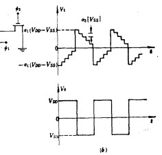
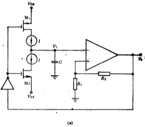
The switched capacitor circuit can also be used to design a switched capacitor multivibrator. The circuit is shown in Figure 6.1-5a. Op amps A1, A2 and capacitor a1C form a positive feedback loop, A1
The switched capacitor circuit can also be used to design a switched capacitor multivibrator. The circuit is shown in Figure 6.1-5a. Op amps A1, A2 and capacitor a1C form a positive feedback loop, A1
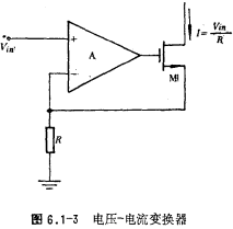
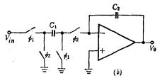
Multivibrator circuit, the actual circuit diagram of Figure 6.1-1 is shown in Figure 6.1-4. The op amp A1 and M2 form a negative feedback loop that converts the input voltage image.png into a current
Multivibrator circuit, the actual circuit diagram of Figure 6.1-1 is shown in Figure 6.1-4. The op amp A1 and M2 form a negative feedback loop that converts the input voltage image.png into a current
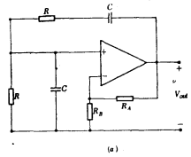
The working principle of multivibrator, MOS operational amplifier is widely used in nonlinear circuits in addition to linear amplification, voltage comparators and various analog filters. This chapter
The working principle of multivibrator, MOS operational amplifier is widely used in nonlinear circuits in addition to linear amplification, voltage comparators and various analog filters. This chapter
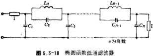
Reduce the parameter table of the low-pass filter, analyze the parameter table of the passive RLC normalized low-pass filter Figure 5.3-16 is the passive RLC low-pass filter with Rs=RL=1 ohm, and its
Reduce the parameter table of the low-pass filter, analyze the parameter table of the passive RLC normalized low-pass filter Figure 5.3-16 is the passive RLC low-pass filter with Rs=RL=1 ohm, and its
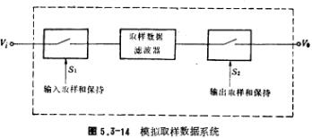
When using a switched capacitor filter, an analog low-pass filter should be connected to the input and output ends of the switched capacitor filter. This is because the switched capacitor filter is an
When using a switched capacitor filter, an analog low-pass filter should be connected to the input and output ends of the switched capacitor filter. This is because the switched capacitor filter is an
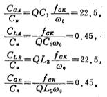
Switched capacitor filter, after the initial design of the switched capacitor filter, the capacitance ratio must be corrected, that is, the adjusted capacitance ratio is scaled to obtain the largest d
Switched capacitor filter, after the initial design of the switched capacitor filter, the capacitance ratio must be corrected, that is, the adjusted capacitance ratio is scaled to obtain the largest d

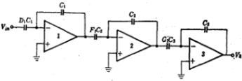
Double second-order switched capacitor filter and circuit structure, previously we discussed using passive RLC network to design switched capacitor filter. This design method is mainly used for low-pa
Double second-order switched capacitor filter and circuit structure, previously we discussed using passive RLC network to design switched capacitor filter. This design method is mainly used for low-pa
Low-pass, high-pass, band-pass circuit design, switched capacitor filter Switched capacitor filter is a novel integrated filter made of MOS operational amplifier, switch and capacitor and other basic
Low-pass, high-pass, band-pass circuit design, switched capacitor filter Switched capacitor filter is a novel integrated filter made of MOS operational amplifier, switch and capacitor and other basic
The basic working principle and design method of switched capacitor filter. Switched capacitor filter is a novel integrated filter made of MOS operational amplifier, switch and capacitor and other bas
The basic working principle and design method of switched capacitor filter. Switched capacitor filter is a novel integrated filter made of MOS operational amplifier, switch and capacitor and other bas


5C1, CD Block, Tianji Building, Tianan Digital City, Futian District, Shenzhen

KIA-The Public