Electronic Technology Forum
Explain the maximum dynamic range and minimum capacitance area of switched capacitor filters in detail
After the initial design of the switched capacitor filter, the capacitance ratio must be corrected, that is, the adjusted capacitance ratio is scaled to obtain the largest dynamic range and the smallest capacitance area. The dynamic range of the switched capacitor filter is defined as 20 log(
 ,here
,here it is the maximum input signal amplitude at the output end of the switched capacitor filter without obvious distortion, which is mainly limited by the saturation working state of the operational amplifier;
 it is the minimum input signal amplitude that can identify the output voltage of the switched capacitor filter from the output noise.It is mainly limited by the op amp and switching noise and the size of the switch feedthrough signal. In general, the maximum dynamic range of a switched capacitor filter is about 80 to 90 decibels. The larger the dynamic range, the stronger the ability of the switched capacitor filter to handle small signals.
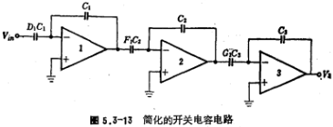
Let's discuss how the switched capacitor filter obtains the largest dynamic range and the smallest capacitance area. To obtain the maximum dynamic range, mainly adjust the output level of each op amp. If the maximum output level of each op amp in the switched capacitor filter remains the same under the action of the input signal, its dynamic range is the largest at this time. The adjustment process of the output voltage of the operational amplifier is usually called scale conversion processing. During the scale conversion process, the transfer characteristics of the switched capacitor filter should remain unchanged. Now take Figure 5.3-13 switched capacitor circuit (for simplicity, the switch is omitted) as an example for description. The transfer function of the circumference is

Assuming that the output voltage V2 is very small, we adjust V1, but the V1 adjustment should not affect the output voltage values of other operational amplifiers. If V1→xV1, the electronic passenger C1 and 1C2 at the output of op amp 1 must be scaled, that is, image.pngimage.png
, At this time, the total voltage gain still satisfies the formula (5.3-39), namely

If the voltage of V2 needs to be adjusted, assuming that the adjustment is y, that is, V2→yV2, then scale the capacitance of the output terminal of the op amp 2, namely (C2, G1C3)→image.png, after this transformation, It has no effect on the output voltage of op amp 1 and op amp 2.
After the above adjustment, the maximum output voltage of each op amp remains the same, that is, xV1=yV2=V3, so that the dynamic range of the circuit is the maximum.

In summary, the scale transformation steps of dynamic range adjustment are as follows:
1. For the output voltage of all internal operational amplifiers, calculate the maximum value VP. Usually, each VP value is simulated and calculated by a switched capacitor network analysis program.
2. Multiply all the capacitances connected (connected via a switch) to the output of the i-th stage op amp ,here
,here Is the maximum output voltage of the i-th op amp. After the capacitor is transformed in this way, the output voltage of the i-th operational amplifier changes from
  to
to  .
.
3. Repeat step 2 for all internal op amps.
In order to obtain the maximum dynamic range, the maximum output voltage of each op amp should be the same.
After completing the scale transformation to optimize the dynamic range, the scale transformation to minimize the capacitance is performed. The method is to divide the capacitors in the switched capacitor filter into several groups. It takes the op amp integration capacitor and the input capacitor as a group. In a group of capacitors, the smallest capacitance is 1 unit capacitance, and the other capacitances are divided by the smallest Capacitors are scaled, and now we still take Figure 6.3-13 as an example. The figure divides the capacitors into three groups, namely
{D1C1C1},{F1C2C2},{G1C3C3}
Find the smallest capacitance in each group, and then perform scale conversion. Assume
D1C1=0.2皮法,C1=1皮法
F1C2=1.2皮法,C2=0.6皮法
G1C3=0.25皮法,C3=0.8皮法
After scale transformation,
D1C1=1单位电容,C1=5单位电容
F1C2=2单位电容,C2=1单位电容
G1C2=1单位电容,C3=3.2单位电容
Obviously, the scale transformation for minimizing the capacitance does not affect the output voltage value of the op amp. Therefore, the scale exchange for minimizing the capacitance will not destroy the scale transformation for optimizing the dynamic range. If the order of these two scale transformations is reversed, the scale transformation for dynamic range optimization will destroy the minimum capacitance characteristic. Therefore, the scale transformation for dynamic range optimization is performed first, and then the scale transformation for capacitance minimization is performed.
After the above-mentioned scale conversion of the switched capacitor filter, each capacitance value is determined, the circuit design is completed, and then the layout design is carried out.
Contact: Mr. Zou
Contact number: 0755-83888366-8022
Mobile phone: 18123972950
QQ: 2880195519
Contact Address: 5C1, Block CD, Tianji Building, Tianan Digital City, Chegongmiao, Futian District, Shenzhen
Please search WeChat official account: "KIA Semiconductor" or scan the following picture to "Follow" official WeChat official account
Please "follow" the official WeChat account: provide MOS tube technical assistance


