Electronic Technology Forum
Circuit analysis of the working principle of MOS integrated multivibrator
In addition to linear amplification, voltage comparators and various analog filters, MOS operational amplifiers are also widely used in non-linear circuits. This chapter mainly discusses the working principle of integrated nonlinear circuits. Non-linear circuits mainly include multivibrators, sine oscillators, time base circuits, modulators and detectors, etc. This chapter mainly introduces the working principle of MOS ops in analog integrated circuits.
In recent years, integration technology has developed rapidly, from monolithic integration to system integration. It can be predicted that the basic circuit introduced in this chapter will become the basic common unit in system integration.
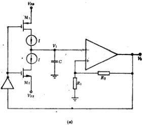
There are many types of multivibrators composed of MOS operational amplifiers. Here we only discuss the MOS multivibrators with relatively simple circuit structure and easy integration. The circuit form is shown in Figure 6.1-1a. It consists of two current sources and It is composed of an op amp, which can generate triangle wave and square wave. The working principle of this circuit is briefly described as follows:
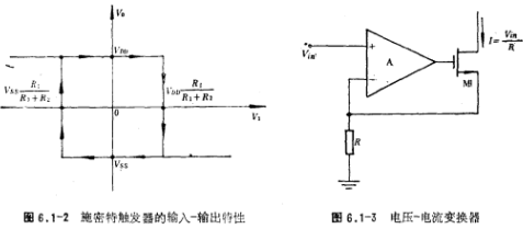
Operational amplifier (used as a comparator) and feedback resistors R1 and R2 form a Schmitt trigger. Suppose the positive limiting level of the operational amplifier output voltage Vo is VDD, and the negative limiting level is Vss. The working principle of the multivibrator. When the op amp input voltage V1 is at a relatively large negative voltage, the op amp output voltage Vo is VDD, this voltage passes through the feedback resistors R1 and R2, and the voltage obtained at the non-inverting input of the op amp is VDDR1/(R1+R2). Before the V1 voltage increases from negative voltage to VssR1/(R1+R2), the output voltage Vo is always at the VDD level. Only when the V1 voltage is slightly greater than VDDR1/(R1+R2), the op amp output voltage Vo changes from VDD Change to Vss, the non-inverting input voltage of the op amp jumps from VDDR1/(R1+R2) to VssR1/(R1+R2). At this time, if the voltage of V1 is greater than the voltage of VssR1/(R1+R2), the output voltage Vo is equal to Vss; if the voltage of V1 is lower than the voltage of VssR1//(R1+R2), the op amp state will circle again and the output voltage Vo changes from Vss to VDD. Figure 6.1-2 shows its input-output conversion characteristics, which can be used to easily obtain triangle waves and square waves.
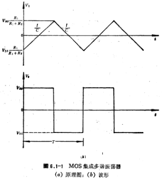
When Vo=VDD, M1 turns on, M2 turns off, the current source I charges the capacitor C, and the voltage of V1 gradually increases from (I/C) t. If V1 reaches VDDR1/(R1+R2), then the op amp The output voltage Vo changes from VDD to Vss, turning off M1. M2 is turned on, capacitor C is discharged, and the discharge current is I. The V1 voltage gradually decreases with the (-I/C) t value. When the Vt voltage drops to VVssR1/(R1+R2), the operational amplifier output voltage Vo rises to VDD. The working principle of the multivibrator. This goes back and forth, the output voltage Vo of the op amp is a square wave, and the input voltage V1 of the op amp is a triangle wave. The waveforms of Vo and V1 are shown in Figure 6.1-1b. According to V1 voltage amplitude and change slope 1/C in the figure. The following relationship can be obtained:

Obtain the oscillation period T and the oscillation frequency f from the above formula, which is expressed as


For VDD=-Vss, the oscillation frequency expression is

In order to turn the circuit in Figure 6.1-1 into a voltage-controlled oscillator (VCO), a voltage-controlled current source can be used instead of the current source I in the figure. In actual circuits, voltage-current converters (Figure 6.1-3) are often used to implement voltage-controlled current sources. The working principle of the multivibrator. The op amp and FET in the circuit in Figure 6.1-3 form a negative feedback loop to ensure that the voltage across the electrograph R is equal to the input voltage , and the current flowing through the MOS tube is equal to
  image.png/R, and 与
 Directly proportional.

Contact: Mr. Zou
Contact number: 0755-83888366-8022
Mobile phone: 18123972950
QQ: 2880195519
Contact Address: 5C1, Block CD, Tianji Building, Tianan Digital City, Chegongmiao, Futian District, Shenzhen
Please search WeChat official account: "KIA Semiconductor" or scan the following picture to "Follow" official WeChat official account
Please "follow" the official WeChat account: provide MOS tube technical assistance


