Electronic Technology Forum
MOS field effect transistor high frequency oscillation circuit, frequency, design analysis
Almost all vacuum tube feedback oscillation circuits can be used in MOS field effect transistor oscillation circuits, and compared with vacuum tubes, MOS field effect transistors have small heat capacity and less heat: Compared with bipolar transistors, its nonlinearity is small, and the input conductivity is small. It is so small that it can be ignored, so good frequency stability can be obtained. Oscillators usually adopt single-gate type, so this section only describes single-gate type circuits.
(1) Basic LC oscillation circuit 33)
There are four basic LC oscillator circuits as shown in Figure 2.48. These circuits are shown in Figure 2.49. They can all be regarded as field effect transistors with feedback circuits in parallel. Therefore, the total y parameter [Y] can be expressed as the sum of the [y] parameter of the field effect transistor and the (y') parameter of the feedback circuit.

Since the four-terminal network is in an oscillating state,

Must be established.
The Colpitts circuit shown in Figure 2.48 (b) can be written as (y') with reference to Figure 2.50
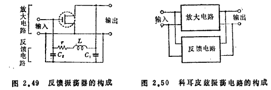

〔Y〕 can be simply viewed as

From the condition that the real part and imaginary part of ▏Y▕=0 are equal to 0, we can get

The frequency and the necessary gm value can be obtained by appropriately omitting the minor items in the two formulas

These oscillation conditions are listed in Figure 2.48, and the voltage feedback rate of the feedback circuit is listed in the bottom column.
The feedback quantity of other circuits is adjusted by changing M (L1/L2 turns ratio, coupling quantity). On the contrary, the feedback quantity of Colpitts type circuit can be controlled by the ratio of C1/C2. The former is suitable for lower frequencies, while the latter is suitable for VHF to UHF bands. MOS field effect transistor high frequency oscillation circuit. In order to stabilize the oscillation operating point and oscillation amplitude, there are the bypass source resistance method and the bias method using DC feedback diodes and leakage resistance.
Oscillation output can be obtained by inductive coupling with a coil used to take out the output signal, or by connecting a coupling capacitor to a drain or gate that is not grounded at high frequency.
(2) The frequency of the oscillator is stable
Oscillator changes include amplitude changes and frequency changes, and the latter is particularly important.
The reasons for oscillator changes include power supply (bias point), changes in load, temperature, humidity, and mechanical vibration. Measures can be taken for the last three reasons, such as improving and compensating the temperature coefficient of LC, preventing moisture, and improving the mechanical structure. The variation of the power supply can cause the variation of some parameters including the nonlinearity of the field effect transistor, thereby changing the oscillation frequency.
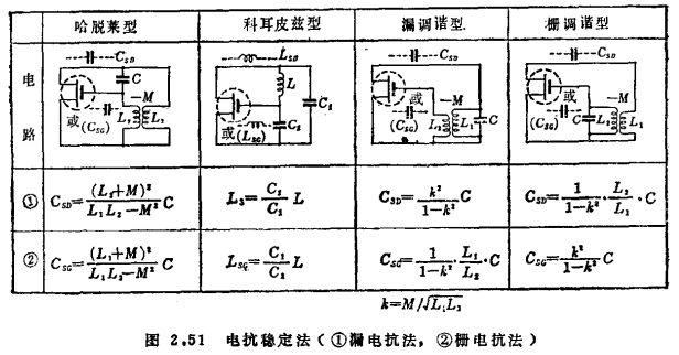
Generally, an oscillator that uses nonlinear negative resistance changes the fundamental frequency according to the content of higher harmonics. In order to avoid this kind of influence, consider or reduce the oscillation amplitude, or increase the Q value of the resonant circuit to prevent the generation of higher harmonics. For example, by using the results obtained by Llewellyn in the research of vacuum tube oscillators, connecting a reactance of an appropriate value in series on the drain or gate can obtain an oscillation frequency that has nothing to do with the nonlinear conductance of the field effect transistor (reactance stabilization method ● ) 34). The appropriate reactance value is shown in Figure 2.51. MOS field effect transistor high frequency oscillation circuit. However, this stabilization method cannot compensate for changes in capacitance parameters. In practical applications, the tuning additional capacitance is large, so it can only be used at lower frequencies.

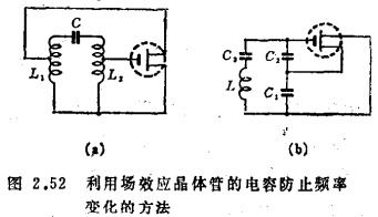
In order to avoid the influence of the input and output capacitance of the field effect transistor, the oscillator can adopt two variant circuits, as shown in Figure 2.52. Figure 2.52 (a) is a modification of the Hartley circuit, the coil has a tap connected to the field effect transistor. Figure 2.52(b) uses L connected in series with a small capacitor C3 to replace L in the Colpitts circuit, which can make C1 and C2 larger, which is called Clapp circuit and is widely used.
The above-mentioned reactance stabilization method is more difficult to adjust, and the method here is contrary to it, and the circuit can be easily constructed in a wider frequency range.
(3) Design of MOS field effect transistor oscillator
As mentioned above, the frequency stability is affected by various factors, so most of them adopt the method of first determining the structure of the oscillator in general, and then designing the oscillator circuit through experiments. Here we introduce the oscillator design method using Hanchet's result 35).
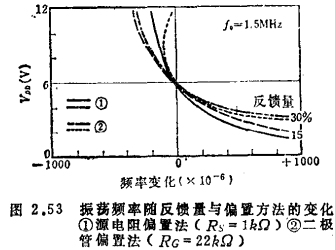
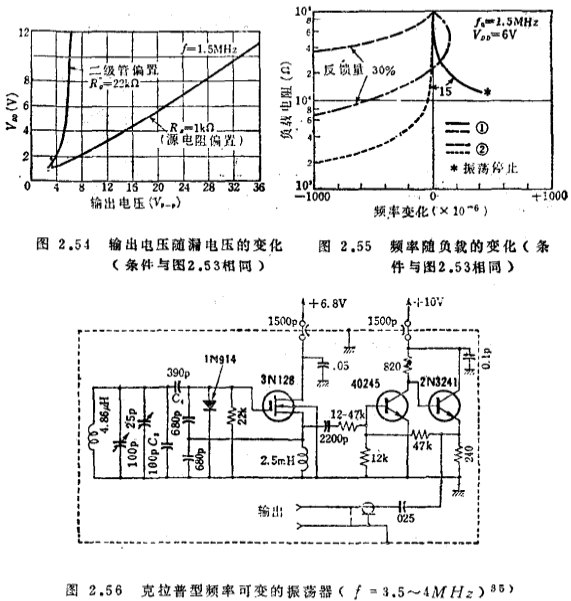
Here we use a 1.5MHz Hartley oscillator for the experiment. First, we change the feedback amount and measure the frequency change with the leakage power supply voltage. The conclusions obtained are: 15% of the feedback amount is appropriate; in terms of frequency stability, the source resistance bias method is better; in terms of the stability of the output amplitude, the DC feedback method is better (see Figure 2.53, 2.54) ). The DC feedback method also shows excellent characteristics in terms of the influence of load changes on frequency stability (see Figure 2.55). MOS field effect transistor high frequency oscillation circuit. The design of other oscillators can also be evaluated in the same way.
As the frequency increases, in order to compensate for the loss, the feedback should generally be larger.
An example of a practical high-stability variable frequency oscillator is shown in Figure 2.56. To stabilize the oscillator. To one end of the voltage divider capacitor is connected to the gate of the field effect transistor; in order to make the oscillator stable and have a low output impedance, a two-stage buffer amplifier is required. From 30 seconds to 2 hours after the power is turned on, the frequency drift value is 30 Hz.
(4) Crystal oscillator
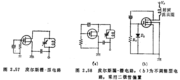
Field effect transistors can also easily constitute crystal oscillators. Figure 2.57 is equivalent to the Pierce grid-cathode circuit of a vacuum tube, and the feedback is through made. At this time, the leakage circuit must be inductive (Hartley type). Therefore, the tuning circuit must be tuned to a frequency higher than the oscillation frequency. Figure 2.58 is equivalent to Pierce's plate-gate type. The drain circuit must be capacitive (Colpitts type), but Coss of field effect transistors can also be used to form the non-adjustable circuit shown in Figure 2.58(b).
In order to obtain harmonic ● oscillation, the circuit is shown in Figure 2.59. The feedback voltage divider circuit composed of C'DC"D is almost unnecessary for the third harmonic oscillation, but it is necessary for the fifth harmonic and the seventh harmonic wave. The tank circuit is not completely affected by the feedback voltage divider circuit. Bypass, C"D/C'D is approximately equal to 3.
Figure 2.60 is an oscillator using a complementary MOS inverter, the oscillation frequency is below 200kHz. MOS field effect transistor high frequency oscillation circuit. It is characterized by working with a micro-power consumption of μW under the power supply voltage of 1.5~15V 30).
Contact: Mr. Zou
Contact number: 0755-83888366-8022
Mobile phone: 18123972950
QQ: 2880195519
Contact Address: 5C1, Block CD, Tianji Building, Tianan Digital City, Chegongmiao, Futian District, Shenzhen
Please search WeChat official account: "KIA Semiconductor" or scan the following picture to "Follow" official WeChat official account
Please "follow" the official WeChat account: provide MOS tube technical assistance


