Electronic Technology Forum
Nodal equation of equivalent circuit of CMOS operational amplifier
Nodal equation of equivalent circuit
The circuit structure and design method of CMOS operational amplifiers are basically similar to bipolar operational amplifiers. However, the consideration of frequency compensation in MOS operational amplifiers is different from that of bipolar operational amplifiers. For the two-stage amplifier shown in Figure 3.0-3, when the capacitor image.png is used for frequency compensation, Figure 3.0-4 can be used. Write out the node equation of the circuit:

Solving the above equation, the transfer function is

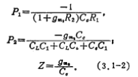
where

It can be seen from the formula (3.1-1) that the equation has two poles (the root of the denominator equation). Due to the function of the compensation capacitor  , the two poles are separated relatively far, that is, one pole is at the low frequency end, and the other pole The frequency is higher. According to this assumption, the poles and zeros of equation (3.1-1) can be obtained as

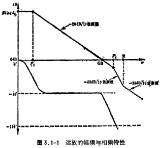
In the formula, P1 is the low-frequency pole, which is the main pole of the operational amplifier, and P2 is the high-frequency pole. It can be seen from the formula (3.1-2) that, due to the function of the compensation capacitor  , P1<P2. If P2>GB (unity gain bandwidth) and Z>P2, then the amplitude-frequency characteristics and phase-frequency characteristics are shown in Figure 3.1-1.

Obviously, the op amp is also stable when the loop is closed to 0 decibels. If no compensation capacitor , Make P1 and P2 very close, so that the op amp is unstable or even oscillate. Compensation capacitor
 to separate the pole frequencies of the op amp, so the compensation capacitor
 it is called a pole division capacitor.
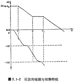
We see that the compensation capacitor is added  later, the pole frequency is pulled apart, but a zero point is also generated, and this zero point is on the right half of the S plane, so the phase shift produced by the zero point is lagging, and it is superimposed with the lag phase shift produced by the poles P1 and P2 , Resulting in a larger additional phase shift. If the frequency of the zero point Z is much greater than the unity gain bandwidth GB, then the contribution of the zero point Z to the phase shift of the op amp can be ignored and does not affect its stability; on the contrary, the frequency of the zero point Z is lower than the unity gain bandwidth GB, then the zero point Z will make The operational amplifier is unstable, and its amplitude-frequency and phase-frequency characteristics are shown in Figure 3.1-2.

Contact: Mr. Zou
Contact number: 0755-83888366-8022
Mobile phone: 18123972950
QQ: 2880195519
Contact Address: Block 5C, CD Block, Tianji Building, Tianan Digital City, Chegongmiao, Futian District, Shenzhen
Please search WeChat official account: "KIA Semiconductor" or scan the following picture to "Follow" official WeChat official account
Please "follow" the official WeChat account: provide MOS tube technical assistance


