Electronic Technology Forum
Constant current source circuit with high output impedance and high swing output
Although the above-mentioned improved constant current source circuit increases the output impedance and improves the constant current performance, when used as an active load, the output swing is smaller. This is because the output stage adopts the cascade form, and the voltage entering the saturation region (Vo) Larger, now take the constant current source circuit shown in Figure 2.2-2 as an example, "For the convenience of discussion, the circuit is redrawn as shown in Figure 2.2-6a. At this time, the output voltage (Vo)-output current (Io) characteristics The curve is shown in Figure 2.2-6b. The drain-source voltage of the M2 tube in the figure , equal to the gate-source voltage
 ,
,
Drain-source saturation voltage of M1 tube ,Therefore, before the M1 tube enters the linear region, the minimum value of the output voltage Vo is

Assuming that the parameters of M1~M4 tubes are the same, the above formula can be written as

and
It can be seen from the above formula that the negative output swing is not only determined by the saturation pressure drop of the tube , Plus the threshold voltage VT.
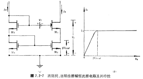
In order to eliminate the VT term in the formula (2.2-7) and increase the dynamic swing of the output voltage Vo, the circuit form shown in Figure 2.2-7a can be used, and a level shift voltage is added between the M1 tube and the M3 tube grid. Source, its value is equal to the threshold voltage VT. After adding the level shift voltage source VT, the drain-source voltage of the M2 tube . Obviously, before the M1 tube enters the linear region, the minimum value of the output voltage Vo is

Figure 2.2-7b shows the output characteristic curve of the circuit of Figure 2.2-7a.

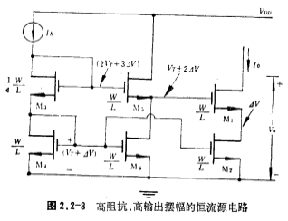
The actual circuit of Figure 2.2-7a is shown in Figure 2.2-8. The bias current of all MOS tubes in the figure is IO (IR=IO). Except for M3 tube, the width-to-length ratio (W/L) of other MOS tubes is equal. same, The width-to-length ratio of the tube is 1/4 of the width-to-length ratio (W/L) of other MOS tubes. For the convenience of writing, the
 .
.

Because the aspect ratio (W/L) of the M2 tube is 1/4 of the aspect ratio (W/L) of other MOS tubes, and according to
 The relational formula is not difficult to prove that such circuit structure and device size,
 The grid potential of the tube is
 , So that the drain-source voltage of the M2 tube
 , To ensure that the minimum output voltage VO is

Figure 2.2-8 The constant current source circuit can be used as an active load to achieve high gain and large output swing.
Contact: Mr. Zou
Contact number: 0755-83888366-8022
Mobile phone: 18123972950
QQ: 2880195519
Contact Address: 5C1, Block CD, Tianji Building, Tianan Digital City, Chegongmiao, Futian District, Shenzhen
Please search WeChat official account: "KIA Semiconductor" or scan the following picture to "Follow" official WeChat official account
Please "follow" the official WeChat account: provide MOS tube technical assistance


