Electronic Technology Forum
Ion implantation method for manufacturing MOS source and drain regions to achieve gate self-alignment
Ion implantation is used to manufacture the source and drain regions of MOS devices to achieve gate self-alignment. Self-aligning mosfet. However, the MOS structure in which the source and drain regions are formed entirely by ion implantation is very undesirable.
First, in order to obtain a lower sheet resistance in the P-doped region, the implanted ion dose is required to be very high (usually greater than 1013pcs/cm2< span style="font-size: 18px;">), which will cause serious damage to the crystal lattice and cause large reverse leakage of the device. If the implant dose does not reach a considerable amount, the sheet resistance of the source and drain regions is very large, causing the device to produce high source-drain strange resistance.

Secondly, because the injected junction depth is very shallow, the source-drain withstand voltage is very low.
These reasons limit the use of ion implantation in doping. Self-aligning mosfet. Currently, a combination of ion implantation and diffusion is used, as shown in Figure 6-11.

First use diffusion technology to make the source and drain of the device to obtain the necessary sheet resistance of the P area, and then use ion implantation to compensate to form the extended part of the P area. As shown in Figure 6-11 (b). Self-aligning mosfet. The aluminum gate is used to protect the gate oxide and at the same time as a mask to implant ions into a predetermined area (called a compensation area) to form a gate self-aligned structure.
When using ion implantation to realize gate self-alignment, you should pay attention to:
①The aluminum gate electrode should be much smaller than the ordinary P-channel process size to leave a compensation area for ion implantation;
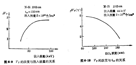
②In order to inject all boron high sons into silicon, accumulate in SiO2 As little as possible, the ion energy should be adjusted appropriately;
③The injection energy of boron is selected in  , phosphorus injection energy is selected
  , The metal layer should also be thick enough;
④In the actual process, the compensation area can range from a few microns to tens of microns, and the oxide layer thickness is 
It must be noted that because the implantation is after the aluminum electrode is formed, the annealing temperature cannot be too high and cannot exceed the aluminum-silicon eutectic point.
Contact: Mr. Zou
Tel: 0755-83888366-8022
Mobile: 18123972950
QQ: 2880195519
Address: 5C1, CD Block, Tianji Building, Tian’an Digital City, Chegongmiao, Futian District, Shenzhen
Please search the WeChat official account: "KIA Semiconductor" or scan the picture below to "Follow" the official WeChat official account
Please "Follow" the official WeChat account: provide MOS tube technical assistance


