Electronic Technology Forum
Analysis of MOS 8-segment decoder structure and logic formula
MOS eight-segment decoder
In today's highly developed electronic technology, the data measured by many electronic instruments can be directly displayed by digital tubes. At present, there are seven-segment and eight-segment digital tubes. Figure 3-17 shows the structure principle of the eight-segment digital tube. It consists of eight light-emitting lines, and each light-emitting element has a corresponding lead-out line. When the lead-out line is at a high level, it will emit light, and when it is at a low level, it will be extinguished. Therefore, you can apply a high level or a low level to each lead wire according to the number to be displayed, and ten numbers from 0 to 9 can be displayed. MOS 8-segment decoder
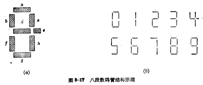
How to display decimal numbers through an eight-segment digital tube requires the help of an eight-segment decoder circuit. Below we will discuss this decoder according to the logic requirements of the data display. Here is still in accordance with the negative logic regulations. When the high level is set to "0", a certain segment of the digital tube will be on (set to the "0" state), and when the low level is "1", a certain section of the digital tube will not be illuminated ( Set to "1" state). MOS 8-segment decoder
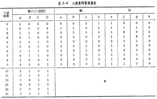
First, according to the requirements of digital display, list the truth table as shown in Table 3-4, and establish a Karnaugh map.
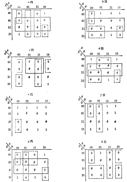
Second, use the Karnaugh map to simplify, and finally write the logical formula. Using the Karnaugh map, the variable "1" can generally be simplified, of course, the variable "0" can also be simplified, and then the logical expression obtained by the simplified can be negated. Below, we simplify the "0". It is also emphasized here that the logical formulas of the paragraphs of a, b, c, d, e, f, g, and h that are written at the end should be the most simple. The number of circuit gates should be as few as possible. However, various factors must be considered in the design and production, so the circuits used are often not in the simplest form. Below we take the actual product  as an example to discuss. MOS eight-segment decoder
Figure 3-18 is the Karnaugh map of the simplification of "0" in each segment of the digital tube.
According to the simplified Karnaugh map, the logical formula of each paragraph can be written and negated:

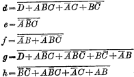
Since the design of parallel gates is more superior than series gates, the logic of each section is changed to the form of "NOR" gates. So:
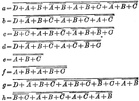
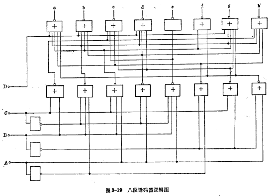
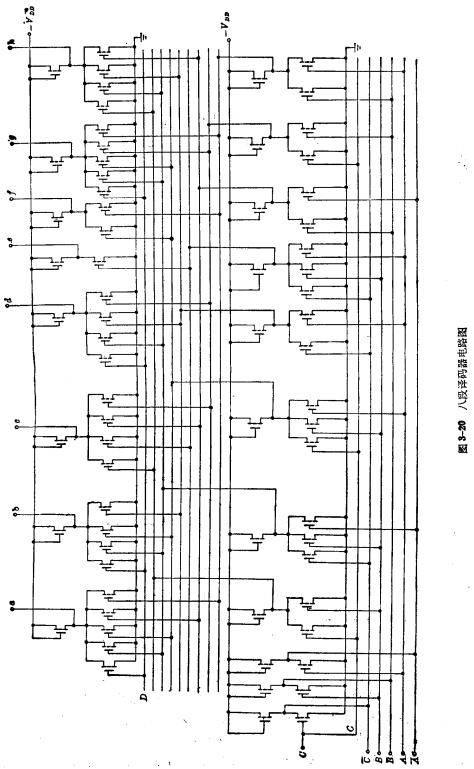
Third, according to the logic formula of each segment, you can draw the logic diagram of input and output (Figure 3-19) and circuit diagram (Figure 3-20).
Contact: Mr. Zou
Contact number: 0755-83888366-8022
Mobile phone: 18123972950
QQ: 2880195519
Address: 5C1, CD Block, Tianji Building, Tianan Digital City, Chegongmiao, Futian District, Shenzhen
Please search WeChat official account: "KIA Semiconductor" or scan the following picture to "Follow" official WeChat official account
Please "follow" the official WeChat account: provide MOS tube technical assistance
Analysis of MOS three-variable decoder structure and logic formula
MOS three-variable decoder, three-variable decoder, three-variable decoder structure


